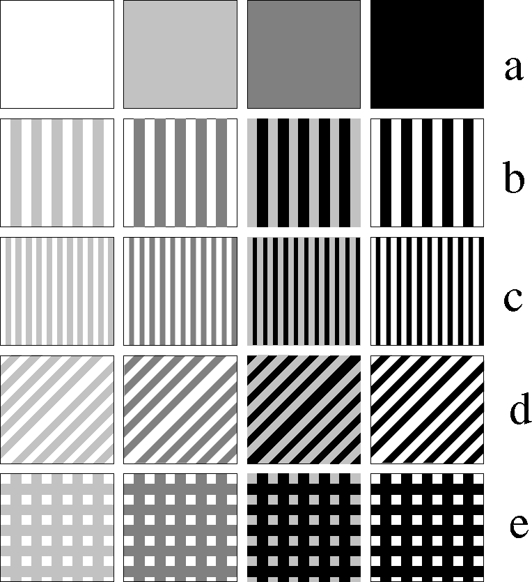
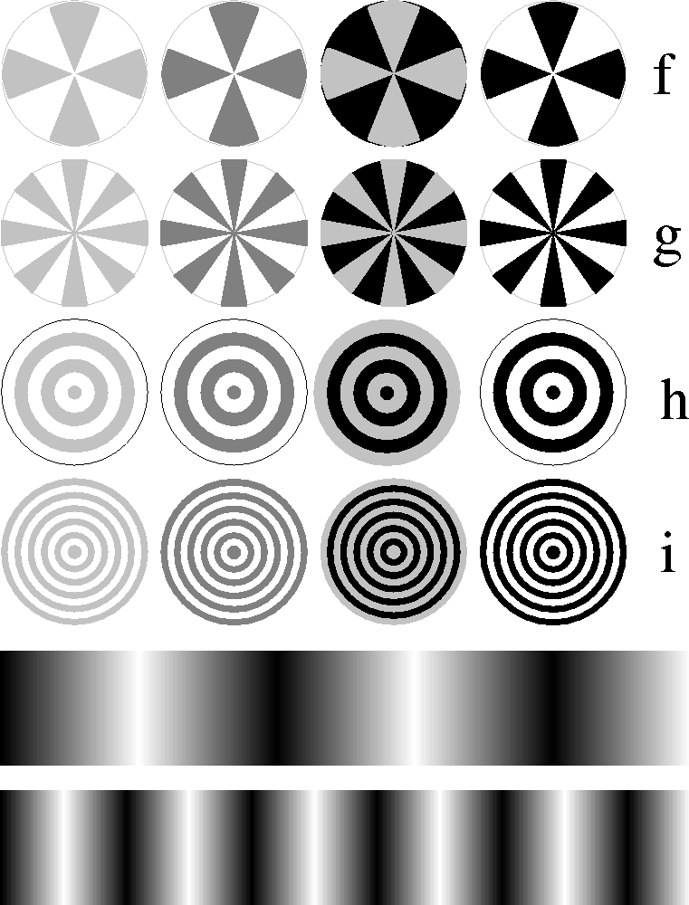
These first set of tests determine the functionality of a vision chip when exposed to stationary patterns. The choice of the size and shape of patterns may be left to the designer, but there are a minimum set of patterns which can be tested without the need for a complicated setup.
Although for motion detection chips steady-state tests may seem unnecessary, under certain condition (for example very low light levels) these chips may produce outputs other than ``no-motion'' output.
Steady-state tests can be divided into several groups as described in the following
All the patterns should be large enough to cover the whole view field of the chip. The above patterns are meaningful only to 2-D vision chips. 1-D vision chips may simply use bar patterns, and sinusoidally shaded patterns.
Some of the test patterns have been shown in Figure 7.46. These patterns can be generated by many graphical editing packages available on PC and Unix workstations. Mathematical packages with graphical capabilities can be also used, almost very easily.
It should be noticed that the final pattern on the chip depends on the characteristics of the optical interface. It is with considering the optical system that a true measurement of spatial processing capabilities can be done.

Figure 7.46: Test patterns for steady-state testing of vision chips.

Figure 7.0: Test patterns for steady-state testing of vision chips.
(continued)