Gruss et al.'s sensor is a range finding chip for parallel light-stripe range detection [Gruss et al. 91]. In light-stripe range sensing methods a stripe of light (usually laser light) is projected onto the scene. The location of the projected stripe on objects, detected by the detector, depends on their range from the projector and the detector. If the geometry of the projecting instrument and the imager is known, range information can be extracted from the location of the reflected stripes in the image. Of course, to obtain a complete range map of the scene the process of projection-and-measurement should be repeated to the desired and achievable resolution. Further details of the method are referred to the reference [Gruss et al. 91].
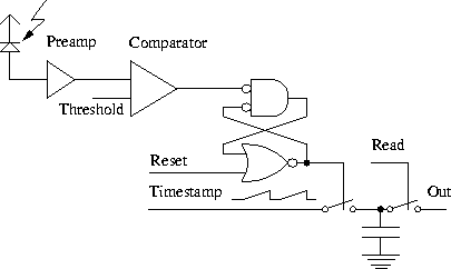
In the VLSI implementation of this method, the presence of the light stripe is detected by circular photodetectors (circular detectors are not sensitive to the rotation of stripes). When the light stripe passes over a photodetector, a current pulse is generated. The position of the pulse, in time, gives a measure of the range (knowing the geometry of projection and detection equipment). The temporal position of the pulse is stamped by a threshold-and-stamp circuit illustrated in Figure 3.27. Using this circuit the output of the chip can be easily associated with the range information.
Two chips have been designed using the same circuit. A 6 ![]() 6
array and a 28
6
array and a 28 ![]() 32 array. Each cell including the photodetector
and processing circuitry occupies an area of about
32 array. Each cell including the photodetector
and processing circuitry occupies an area of about ![]() , of which a quarter is used by the circular
photodiode.
, of which a quarter is used by the circular
photodiode.

Figure 3.27: The time-stamp circuitry.