McQuirck has designed a CCD/CMOS chip for estimating the focus of expansion (FOE) [McQuirk 96a, McQuirk 96b]. The algorithm which has been implemented in the chip tries to minimize the depth Z with constraints on the value of the translation vector t. In this process points in the image which have a higher temporal variation are given smaller weights and points which are steady or have small variation are given large weights, as these points are more likely to be the FOE point. Solving the derived equations requires pixel interaction from the whole image, which is not feasible. Also the large number of variables to be calculated at each pixel inhibits a fully parallel analog VLSI implementation. Therefore, a discrete-time iterating method (which can easily be implemented in CCDs) is used for solving the equations.
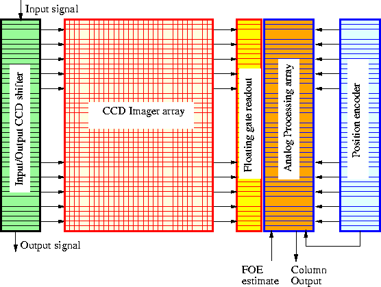
The chip comprises a two-dimensional array of CCD interline imagers, and a one-dimensional array of analog signal processing elements. The interline imager can provide two image frames at the same time, so that temporal gradients of the image can be calculated. The output of the imager array is scanned and passed through floating-gate CCD read-out circuits. Then CMOS circuits are used for implementing various functions required in the processing. The position encoder provides the position of the current pixel. The estimate of the FOE is calculated off-chip and is fed back to the processing array.
All the circuits are designed using differential current-mode techniques in the above-threshold regime. The chip architecture is shown in Figure 3.26.
The chip has been designed in a 2 ![]() m CCD/BiCMOS process from Orbit.
The chip has 64
m CCD/BiCMOS process from Orbit.
The chip has 64 ![]() 64 pixels with a size of
64 pixels with a size of ![]() . This large pixel size has been determined by the pitch of the
analog processing array.
. This large pixel size has been determined by the pitch of the
analog processing array.

Figure 3.26: Architecture of McQuirk's FOE chip. Using the CCD shifter at
the left the image from the imager can be read out, and also
synthetic images can be applied to test the analog processing
array.