Sarpeshkar et al.'s motion detector described in [Sarpeshkar et al. 93] is an implementation of Reichardt's model for motion detection, in which the signal from one input channel is delayed and correlated with its neighbors. A zero-crossing edge detector (See section 3.6) finds the edges. The edges pertaining to positive and negative gradients (LE and RE) are separated and applied to separate motion detection units (See Figure 3.28).
The motion detection unit has the generic DSMD (directionally selective motion detector) structure, with two EMD (elementary motion detector) units and a subtracter. Two major building blocks used in this chip are shown in Figure 3.29. The circuit in Figure 3.29-a is the schematic of the DSMD. The signal from two neighbors are passed through two branches of pulse shaping circuits, one of which introduces a delay to the pulse (the branch with D and P boxes). The comparison of a signal from the delayed signal of the neighbor is done using a NAND structure. The outputs of the two NAND structures are subtracted using a simple current mode subtracter, from which an output current pulse is produced depending on the direction of motion.
The pulse shaping circuit shown in Figure 3.29-b generates an output pulse which is delayed by a value depending on the biasing current ID and the capacitance C2.
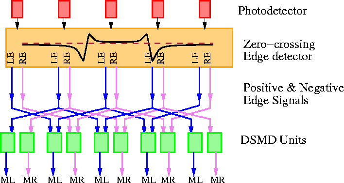
Figure 3.28: Architecture of Sarpeshkar et al.'s motion detector.
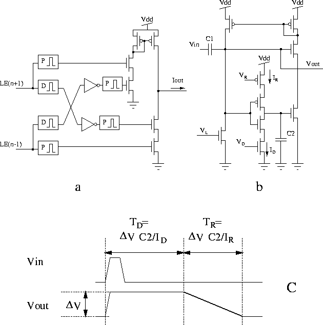
Figure 3.29: a) Schematic of a DSMD. b) Circuit diagram of a pulse shaping
circuit. VL, VD, and VR determine the threshold, pulse
width, and an unusable period after pulse generation. For proper
operation IR < ID. c) Shape of the output waveform. Note that
if another input pulse comes before the period TR ends, a
different duration of TD for the next pulse will be obtained.
Also if IR>ID, the circuit becomes oscillatory.