This vision chip detects the position and orientation of an object [Standley 91b]. The chip first computes moments of the image using a resistive grid. These moments are then used to find orientation and position of an object in the image.
The zeroth and first order moments of an object are defined by
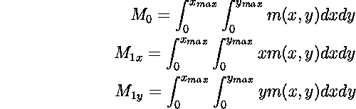
The theory and algebra from which it is postulated that using a
resistive network (whose inputs are currents injected into the
network, and whose outputs are the currents flowing to the periphery
of the grid in four sides of the array) these moments can be computed,
can be found in Standley's thesis [Standley 91a]. In this
process the dimension of data is reduced by one order (from 2D to four
1D). The process of data reduction is in fact done twice. Once from
within the 2D array to the 1D boundaries, and then from the 1D
boundaries to four corners. The chip architecture is shown in
Figure 2.17. The input to the 30 ![]() 30
resistive grid array is provided by a 29
30
resistive grid array is provided by a 29 ![]() 29 array of
photodetectors. The resistive grid is implemented using passive
polysilicon resistors. Photodetectors are parasitic bipolar
transistors. The photo-generated currents are thresholded to eliminate
the slow response time of dark pixels. The boundary of the 2D array is
connected to a virtual ground. The current flowing into the boundary
of the 2D array is sensed and buffered by a 1D array of current sense
and buffer circuitry. The buffered current is then switched into one
of two 1D resistive grids, one with uniform resistors and the other
with quadratic resistors, which are linearly graded with respect to
their position from origin (lower-left corner of the chip). The ends
of the 1D resistive grids are finally connected to virtual grounds,
where the currents can be measured. From the measured currents, the
first moment of the image, for example, can be obtained using the
following equations.
29 array of
photodetectors. The resistive grid is implemented using passive
polysilicon resistors. Photodetectors are parasitic bipolar
transistors. The photo-generated currents are thresholded to eliminate
the slow response time of dark pixels. The boundary of the 2D array is
connected to a virtual ground. The current flowing into the boundary
of the 2D array is sensed and buffered by a 1D array of current sense
and buffer circuitry. The buffered current is then switched into one
of two 1D resistive grids, one with uniform resistors and the other
with quadratic resistors, which are linearly graded with respect to
their position from origin (lower-left corner of the chip). The ends
of the 1D resistive grids are finally connected to virtual grounds,
where the currents can be measured. From the measured currents, the
first moment of the image, for example, can be obtained using the
following equations.

The chip has been fabricated in a 2 ![]() m CMOS process in an area of
7.9mm
m CMOS process in an area of
7.9mm ![]() 9.2mm, and contains an array of 29
9.2mm, and contains an array of 29 ![]() 29 cells
occupying a total area of 5500
29 cells
occupying a total area of 5500 ![]() 5500
5500 ![]() .
.
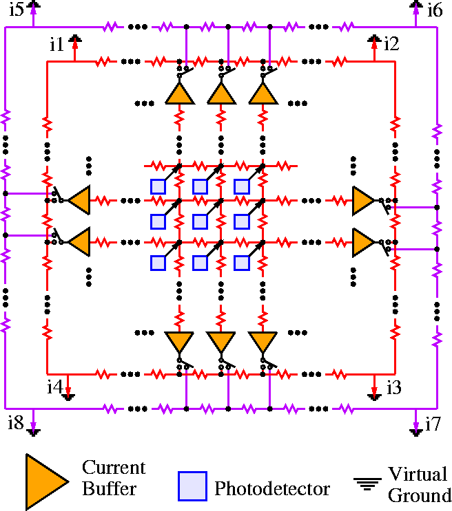
Figure 2.17: Architecture of Standley's vision chip.