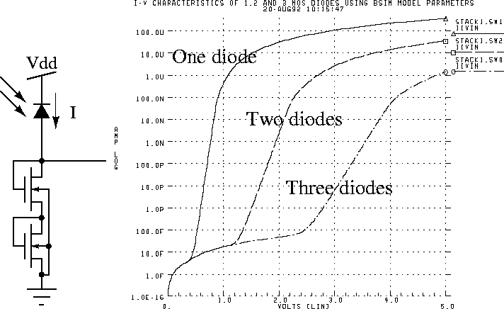
The simplest circuit for converting the photocurrent to voltage is the logarithmic conversion circuit shown in Figure 7.15. The logarithmic function is a result of the subthreshold operation of the diode connected MOS transistors. As the input photocurrent is usually very small and falls within the subthreshold region of a MOS diode, the current-voltage relationship is determined by

where W and L are the width and length of the transistor,
respectively, I is the input photocurrent, n is the
subthreshold slope factor, ![]() is a process dependent parameter,
and V is the output voltage. This circuit has been the
workhorse of many vision chips. In many designs this circuit is used
because of its small size and, and large dynamic range. At low light
levels, however, the circuit illustrates a very slow response, which
necessitates longer settling times.
is a process dependent parameter,
and V is the output voltage. This circuit has been the
workhorse of many vision chips. In many designs this circuit is used
because of its small size and, and large dynamic range. At low light
levels, however, the circuit illustrates a very slow response, which
necessitates longer settling times.
A disadvantage of this circuit is the extreme compression on the input signal. If the implemented algorithm needs to differentiate between signals, the logarithmic compression reduces the chance to detect such differences. This is specially true for motion detection chips. When the contrast of the input image is low, the logarithmic compression reduces the contrast to such low levels that in many cases only very large contrast edges can be detected.

Figure 7.15: A logarithmic photocircuit with two series MOS diodes.
Simulation results for three cases.