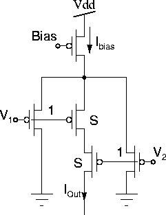
Stereo correspondence between two images of a scene captured at different angles requires a similarity (or dis-similarity) measure between pixels in each image. Instead of using conventional distance measures, such as Euclidean distance and city block distance, Gamze Erten has used a hardware measure based on Delbruck's bump circuit shown in Figure 4.3 [Erten 93, Erten and Goodman 96, Erten and Salam 96].

Erten shows that this similarity measure gives a better statistical distribution than the other two measures.
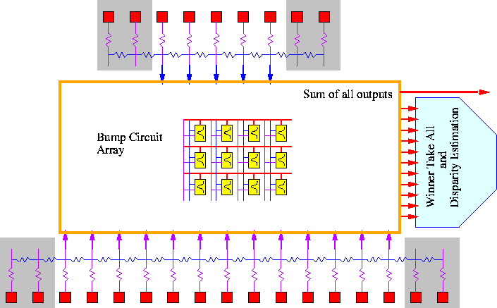
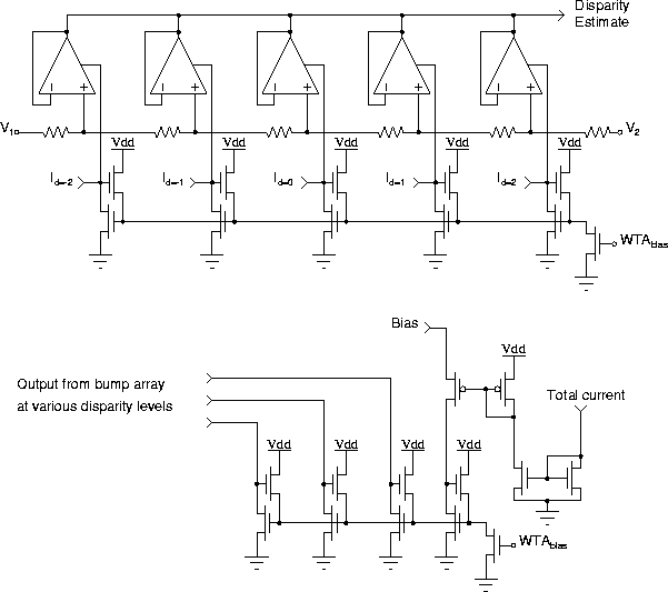
This stereo correspondence chip receives two 1D images and finds the disparity. The chip architecture is shown in Figure 4.4. The winner-take-all circuit is followed by a position encoder, which finds the position of the winner cell. In order to increase the confidence in the output of the operation a ``cofidence circuit'' is designed which checks the value of a confidence metric against a threshold. The confidence metric used in the implementation is the division of the value of the winner cell by the sum of all outputs of the bump array. The schematic diagram of the WTA and confidence circuits are shown in Figure 4.5.
The chip has been designed and fabricated in a 2 ![]() m 2P-2M CMOS
process. It has nine inputs for the right image and nineteen inputs
for the left image. The design if fitted in a TINY chip
(2.2mm
m 2P-2M CMOS
process. It has nine inputs for the right image and nineteen inputs
for the left image. The design if fitted in a TINY chip
(2.2mm ![]() 2.2mm). Successful test results have been reported in
the references.
2.2mm). Successful test results have been reported in
the references.

Figure: Delbruck's bump circuit for measuring the similarity between
two values. [Delbrück 91, Delbrück 93a].

Figure 4.4: Architecture of Erten's stereo correspondence chip. The
outputs of the cells in the shaded areas are not used in the
comparison operation to avoid edge effects.

Figure 4.5: Top: the WTA circuit with position encoder. Bottom: The
confidence circuit.