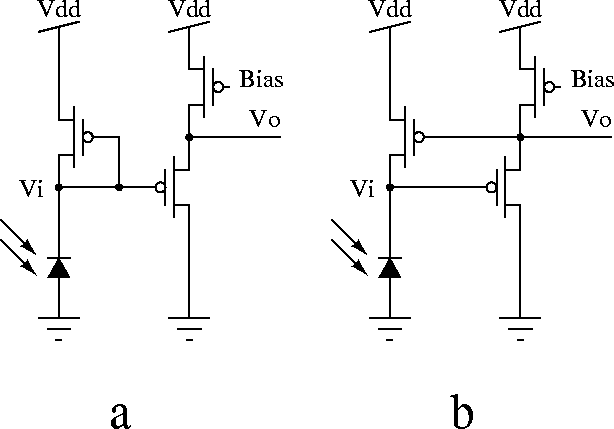
The simple logarithmic circuit described in section 7.3.3 can be used with a buffer having a gain equal to or less than one, instead of the amplifier (Figure 7.18-a). In this case the circuit does not show significant dynamic improvement, and in fact it shows a slight degradation (this can be easily checked by the equation derived in section 7.3.3 ). However, the output now is buffered using the source follower stage.
This circuit is idealy suited for driving large capacitive loads at
the output. The advantage of the circuit shown in
Figure 7.18-b over the simple buffering
method in Figure 7.18-a is that the
output voltage at Vo does not depend on the DC characteristics
of the source follower buffer. Also the output voltage at Vo of
the simple buffering method experiences a voltage drop of
approximately ![]() , the threshold voltage of the MOS transistors.
, the threshold voltage of the MOS transistors.

Figure 7.18: Schematic of the buffering photocircuits a) using the simple
method, and b) using the buffered photocircuit.