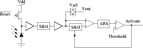
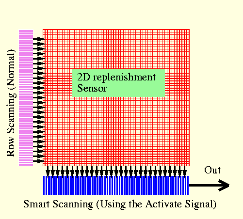
Aizawa et al. describe an image sensor which comprises sensor level compression [Aizawa et al. 94, Aizawa et al. 95], which significantly reduces the amount of image data to be read out. The compression algorithm is based on conditional replenishment [Jain 89], in which the pixel value is compared with the previously sampled and stored value (See Figure 3.31). If the result of comparison exceeds a threshold, the Activate signal is activated which controls the scanning logic, when the row containing that cell is scanned. The scanning logic bypasses all inactive cells and only reads out the pixel value of activated cells, hence reducing the scanning time.
The compression ration depends on the contents of the image and the
frame rate. For very high frame rate applications, ratios of about 100
can be obtained. For normal applications, ratios of about 10 are
obtainable. The 2D array of 32 ![]() 32 elements has been fabricated
using a 2
32 elements has been fabricated
using a 2 ![]() m CMOS process. Each cell occupies an area of
170
m CMOS process. Each cell occupies an area of
170 ![]() m
m ![]() 170
170 ![]() m.
m.
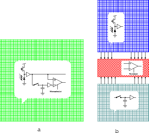
In [Hamamoto et al. 96b, Hamamoto et al. 97] a column parallel architecture for the compression sensor is described. In these new sensors the photodetector and storage elements are separated into two two-dimensional arrays. The processing element, which only occupies one column, is located between the two arrays (See Figure 3.33). This method brings with it several advantages including: increased density and fill factor for the detectors, and reducing the number of processing elements to only one column. This architecture suits well to those algorithms which operate on individual pixels or a neighborhood in the y direction (the direction of the processing element column).

Figure: Schematic of a pixel in the Aizawa et al.'s image compression
sensor.

Figure: Architecture of Aizawa et al.'s compression
sensor.

Figure 3.33: a) Pixel parallel architecture, with
photodetector, storage element, and processing element in each
pixel. b) Column parallel architecture, with separated arrays for
photodetectors, memory and processing element.